Showing posts with label CAD Tip. Show all posts

Monday, May 2, 2022

Sunday, May 1, 2022

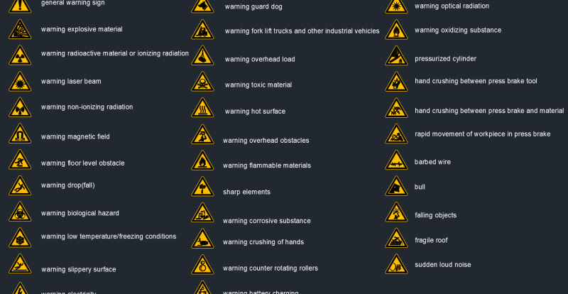
Auto CAD free Block- Hazard Warning Signs

Auto CAD free Block- Hazard Warning Signs

Auto CAD free Block

warning signs, warning danger sign, warning safety signs, warning hazard sign are recognizable symbols designed to warn about hazardous or dangerous materials, locations, or objects, including electric currents, poisons, and radioactivity. The use of hazard symbols is often regulated by law and directed by standards organizations.


Friday, September 18, 2020

Toilet Drawing Plan and Sections

Toilet Drawing Plan and Sections

 Toilet plan and section 2D AutoCAD Drawing for Interior Design Classic And Modern CAD Blocks, Free download in dwg file formats for use with AutoCAD and other 2D design software without Login request.


Wednesday, July 15, 2020

AutoCAD Constraint

AutoCAD Constraint

This is the most Auto CAD using Person asking how to do this Auto CAD Constraint Correction 
If you are working with a CAD file and you keep getting this annoying constraint symbol which also slows down AutoCAD when you select any object here is how to remove it:


This is the Methode of how to do it.

Right-click on the symbol, either select “Hide All Constraints” to hide all the constraints or choose “Constraint Bar Settings” to individually pick which constraint to hide. The constraint bar settings will show you all the available settings that you can modify.


NB: Choosing “Hide all constraint” will hide them once but it will not prevent them from showing up again. To completely hide them use the Constraint Bar setting and select “Infer geometric constraints“. That should fix your problem.

Sunday, May 10, 2020

How to Create a XREF Drawing in Auto CAD

How to Create a XREF Drawing in Auto CAD

Xref is the most useful command from AutoCAD. If you are going to use the software for work or you are looking to advance further, you will need to know how to use the xref command. It is absolutely necessary. And I will show you why.
Xref is used to cross reference plans and objects because you want to minimize repetitions, maximize consistency, save time and increase productivity.
Now, let us become more practical here. Let us assume you have three drawings. I will call them sheet 1, sheet 2 and sheet 3 (see images below).


Sheet 1 shows a rectangle. But it could be anything else.( In using Auto CAD it will be one of our Drawing A) The two other sheets have circles, etc., but they both have one thing in common: a rectangle. So instead of drawing that rectangle twice, it would be wise to draw it once and xref it to both drawings. Some of you might think: What if I draw it once and then copy it to each drawing?
If you copy the drawing you will have to copy it again if you want to make changes to that rectangle. Let us say you want to make it larger or want to chamfer the edges. Do you want to copy again? Or do you want to just change the xref and that is it.
The idea here is to reduce steps and time by drawing anything in common once. And that is when the xref comes in handy.

There are two types of xrefs: Overlay and Attachment.


Overlay: only brings what you draw inside that xref sheet. No other dependent. In other words: if you were to look at a tree diagram, it only goes one level deep (see image above on the left).
Attachment xrefs bring unlimited dependent xrefs and levels (see image above on the right).

This is quick Step

Steps:
1. Type XREF at the command line to bring the dialogue box.
2. Right click and select Attach DWG.
3. Browse for the drawing you want to xref.
4. Select Open.
5. Pick Overlay or Attachment.
6. For the path, choose Full path for this tutorial.
7. For insertion point, scale and rotation: leave them unchecked for this tutorial.
8. Click OK and close the dialogue box.


Then Your xref drawing should be inserted inside the current drawing like the above image.



Saturday, May 9, 2020

Quick tip For Enable CAD Menu Bar

Quick tip For Enable CAD Menu Bar

A quick tip for enabling your Menu bar is to type MENUBAR in your command area


and set the value to one (1). A value of zero (0) will turn the Menu bar off.


You can also right-click on the Menu bar and deselect it to turn it off.


Saturday, June 22, 2019

Unable to Edit your Drawing Text on Auto CAD ?

Unable to Edit your Drawing Text on Auto CAD ?

Issue
You cannot enter or edit text in your drawing.


Cause
You may have the MText Editor (MTEXTED) system variable set to something other than NONE/Internal.


Solution

Type MTEXTED in the Command line and press Enter.


When prompted to Enter new value, type a period (.).


The MTEXTED variable should now be set to NONE/Internal, and you should now be able to place or edit text.

How to Fix  Auto CAD Error Creating Text

How to Fix Auto CAD Error Creating Text

Error Creating Text Style '(text style name)': Font File '(font name)' Not Installed (Using a Land F/X Tool, or Placing Text)

Issue
You received an error message similar to the following when trying to use a particular font in a drawing:

Error creating text style "(font)": Font file "(font)" not installed.


For example, if you attempted to create a zone or Work Area and your Zone Text Style is set to a Swiss font, you might receive the message: Error creating text style "ZONE": Font file "swiss.tff" not installed.


Cause
You are attempting to use a font that is either:


  • Not installed on your computer, or
  • An Open Type font (OTF), which AutoCAD does not support


To determine the exact issue with the font you're trying to use, check the file extension of the font file listed in the error message.


If the font name has a file extension other than .otf, such as .tff, the font is most likely not installed on your computer.


If the font name has a .otf extension, it's an OTF font, which AutoCAD doesn't support.


Land F/X tools and our default Text Styles:
If you're using a Land F/X tool that requires the placement of text, the Land F/X Text Style associated with that tool is currently assigned to a problematic font. The two examples pictured above show two potential errors you might see when trying to place, or use a tool associated with, the ZONE Text Style. In this case, the ZONE style applies automatically to text placed in a drawing through the use of our Work Area tool and Zoning callouts.


Solution

1. Open the General Preferences screen:

                                                              F/X Admin ribbon

                                      Preferences flyout buttons on any of the other F/X ribbons


                                      Several toolbars (FX Admin toolbar pictured)

    Any of the F/X pull-down menus

(F/X Admin, F/X Graphics, F/X Planting, F/X Irrigation, or F/X Details)

                                               or type *FXPreferences in the Command line


2. In the General Preferences screen, highlight the problematic Text Style (example: Zone), and click Edit to open the Text Manager.


3. In the Text Manager, select a different font.

Each font you see in the list will be both installed on your computer and not an OTF style. Any font you choose will resolve the issue.


In our example, we'll assign the font Arial to the ZONE Text Style.


Click OK to save the change.


You should now be able to use the Land F/X tool or place text without seeing the error.


Wednesday, June 19, 2019

Error Correction of Installing Auto CAD: Please Install DirectX Before Installing AutoCAD (Installing F/X CAD)

Error Correction of Installing Auto CAD: Please Install DirectX Before Installing AutoCAD (Installing F/X CAD)

You received the following error while attempting to install F/X CAD:
Error: Please install DirectX before installing AutoCAD (year version)


Solution

Locate the installer folder on your desktop. This folder's name will start with fxcad. Double-click this folder to open it.

Inside the folder, open the folder named 3rdParty, then open the folder named DirectX.


Double-click the file named DXSETUP.exe to run it.


You can now continue installing F/X CAD.


Friday, May 3, 2019

Aoto CAD OSNAP Command

Aoto CAD OSNAP Command

When you are drafting it is best to use your OSNAP. It snaps automatically the cursors to End point, Intersection, Midpoints, etc.. I think it is very difficult to edit a drawing without the OSNAP turned on. The OSNAPs can be accessed by using “shift/right click” or by typing OSNAP at the command line.


Within the OSNAP settings you have the option to check all the modes you need.